
How to Calculate Coil Processing Line Capacity for Your Production Needs
Understanding Coil Processing Line Capacity: A Practical Calculation Guide
Selecting the right coil processing line for your factory is one of the most consequential equipment decisions you will make. A line that is undersized creates a perpetual bottleneck, while an oversized line ties up capital in unused capability. The key lies in accurately calculating your required line capacity before you commit to a purchase. This guide walks through the essential formulas, parameters, and real-world considerations that go into a proper capacity calculation.
What Is Coil Processing Line Capacity?
In practical terms, coil processing line capacity is the maximum throughput a line can achieve under normal operating conditions, typically measured in tons per shift or tons per year. Unlike a simple machine rating, line capacity accounts for the interaction between individual stations—uncoiler, leveler, shear or slitter, stacker or recoiler—and the downtime between coils.
Manufacturers often quote theoretical line speeds in meters per minute, but real-world throughput is almost always lower. Understanding the gap between theoretical speed and practical capacity is what separates a well-sized line from a costly mistake.
Key insight: A line rated at 80 m/min may only achieve 40–55 tons per shift depending on coil weight, material thickness, and changeover frequency. Always calculate effective capacity, not theoretical speed.
The Core Capacity Formula
The fundamental equation for calculating coil processing line throughput is straightforward:
Effective Capacity (tons/shift) = Operating Time × Line Speed × Material Density × Utilization Factor
Let us break each component down into measurable parameters that you can plug in with your own production data.
1. Operating Time Per Shift
Start with the total available time in a shift, then subtract planned downtime:
- Standard shift: 480 minutes (8 hours)
- Breaks and meetings: Typically 20–30 minutes
- Planned maintenance: 10–15 minutes per shift
- Net operating time: 435–450 minutes
Use the lower end of the range for conservative planning and the higher end for optimistic scenarios.
2. Material Variables: Thickness, Width, and Density
The physical dimensions of your coil stock directly determine how much material passes through the line per unit of length:
- Coil width (W): Measured in millimeters. Wider coils increase throughput proportionally.
- Material thickness (T): Measured in millimeters. Thicker material increases weight per linear meter but may reduce maximum line speed.
- Material density (ρ): Steel ≈ 7,850 kg/m³, Aluminum ≈ 2,700 kg/m³, Stainless steel ≈ 7,930 kg/m³
The weight per linear meter is calculated as:
Weight per meter (kg) = W (m) × T (m) × ρ (kg/m³)
For example, a 1,200 mm wide × 2.0 mm thick mild steel coil weighs approximately 18.84 kg per linear meter.
Determining Line Speed Parameters
Line speed is rarely a single number. Different operations impose different speed constraints.
Shearing Line Speed
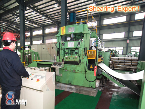
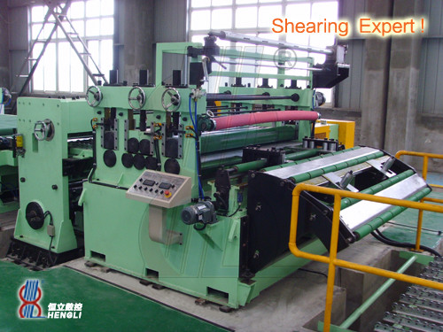
For cut-to-length and flying shear lines, the effective speed depends on the cutting cycle:
- Maximum mechanical speed: The fastest the line can run continuous material (e.g., 80 m/min)
- Cutting cycle limitation: At shorter cut lengths, the shear mechanism becomes the bottleneck
- Acceleration/deceleration: Each coil start and stop cycle reduces average speed
Formula for average shearing speed:
Average Speed = (Cut Length × Cuts per Minute) / 60
Where cuts per minute is limited by the shear mechanism cycle time
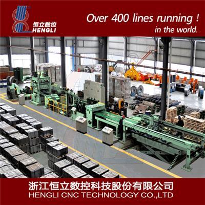
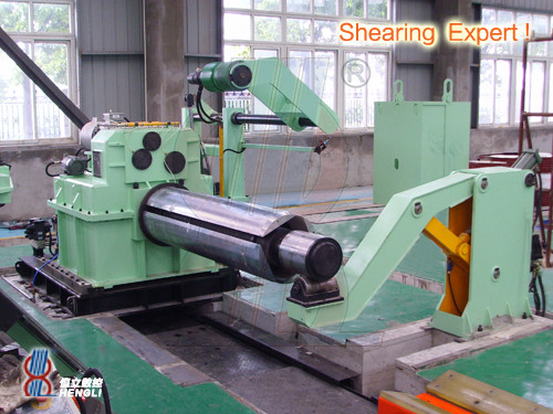
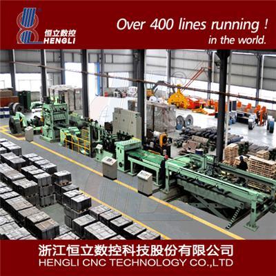
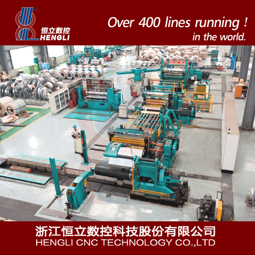
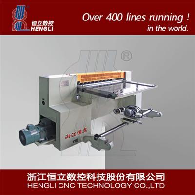
Related Products: Cut-to-Length Lines
Slitting Line Speed
Slitting lines face different constraints. The effective speed depends on the balance between the uncoiler and recoiler tension control, strip guiding accuracy, and knife clearance setup:
- Typical range: 60–150 m/min for conventional slitting
- High-speed precision lines: Up to 300 m/min for thin-gauge material
- Key constraint: Strip stability at higher speeds—material wandering or edge wave can force speed reduction
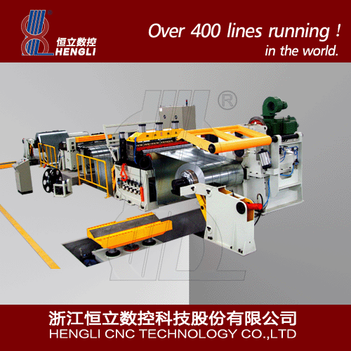
Related Products: Slitting Lines
Coil Changeover Time and Its Impact
One of the most frequently underestimated factors in capacity calculations is coil changeover time. Every time a coil runs out, the line must stop for unloading, loading, threading, and setup:
Common mistake: Assuming 5-minute coil changes. In reality, changeover time ranges from 8 to 25 minutes depending on coil weight, handling equipment, and operator experience.
The number of coil changes per shift is:
Coil Changes = (Operating Time × Utilization) / (Run Time per Coil + Changeover Time)
Where run time per coil = coil weight (tons) / (line speed × material weight per meter × 60). A 10-ton coil running at 60 m/min with 18.84 kg/m yields about 8.85 minutes of run time. With a 12-minute changeover, each coil cycle takes nearly 21 minutes—meaning changeover time dominates the cycle.
Step-by-Step Capacity Calculation Example
Let's work through a real-world example for a cut-to-length line processing automotive-grade steel.
Input Parameters
| Parameter | Value | Notes |
|---|---|---|
| Material | Mild steel | ρ = 7,850 kg/m³ |
| Coil width | 1,250 mm | 1.25 m |
| Coil thickness | 1.5 mm | 0.0015 m |
| Coil weight | 15 tons | Typical |
| Line speed | 60 m/min | Average |
| Cut length | 2,000 mm | 2 m per blank |
| Changeover time | 12 min | Measured |
| Shift length | 480 min | 8 hours |
| Planned downtime | 35 min | Breaks + maintenance |
Calculation Steps
- Weight per meter: 1.25 × 0.0015 × 7,850 = 14.72 kg/m
- Run time per coil: 15,000 kg / (60 m/min × 14.72 kg/m) = 16.98 minutes
- Coil cycle time: 16.98 + 12 = 28.98 minutes
- Net operating time: 480 − 35 = 445 minutes
- Coils per shift: 445 / 28.98 = 15.35 coils (round down to 15)
- Throughput per shift: 15 × 15 tons = 225 tons per shift
- Annual capacity (2 shifts, 300 days): 225 × 2 × 300 = 135,000 tons/year
Estimated annual throughput: ~135,000 tons
Assuming 2 shifts, 300 working days, and 85% line utilization
Material-Specific Considerations
Different materials behave differently on the same line, and your capacity calculation must account for this.
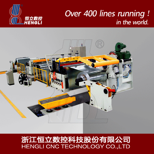
Silicon Steel (Electrical Steel)
Silicon steel requires careful handling to avoid edge burrs and interlamination shorts. Lines running silicon steel typically operate at 40–70% of their maximum speed when processing standard carbon steel. The material's brittleness also increases setup time for knife clearance adjustments.
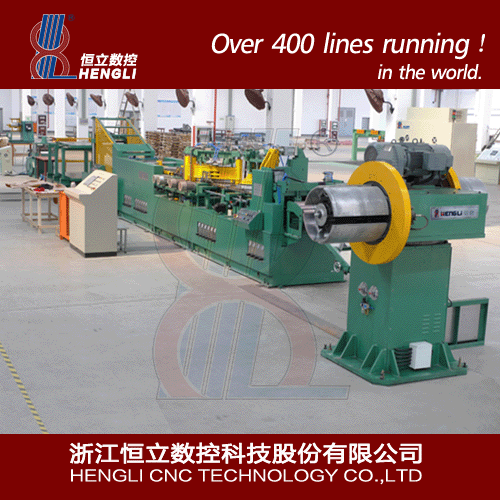
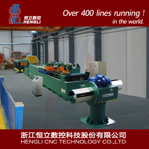
Related Products: Silicon Steel Processing Lines
Aluminum and Tinplate
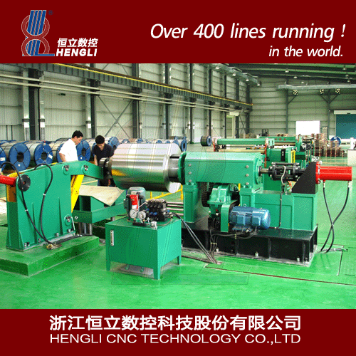
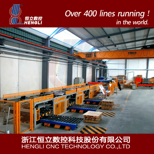
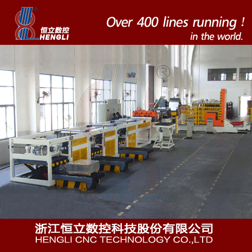
These softer materials allow higher line speeds but demand tighter tension control and more frequent knife changes. Tinplate's thin gauge (typically 0.15–0.35 mm) increases the linear meters per coil, meaning fewer coil changes but more critical tension management.
Related Products: Tinplate & Aluminum Scroll Cutting Lines
Stainless Steel
Stainless steel's work-hardening properties reduce permissible speed and increase power consumption. Lines processing stainless steel often need 15–25% derating from their carbon steel capacity rating.
Slitting Line Capacity: Additional Factors
For slitting lines, capacity depends on the number of slit strands. The key formula adjusts for strand count and recoil limitations:
- Throughput per strand: Total throughput divided by the number of slit strands
- Recoil tension limit: The recoiler may become the bottleneck when slitting into many narrow strands at high tension
- Knife setup time: Arbor setup for multi-strand slitting typically adds 15–30 minutes per setup change
When calculating slitting line capacity, multiply the base line throughput by a strand efficiency factor (typically 0.85–0.95 for most configurations).
Related Products: Slitter Machines
Practical Tips for Accurate Capacity Planning
Track Real Data
Record actual cycle times, changeover durations, and downtime for at least two weeks. Use measured data rather than equipment specifications for capacity calculations.
Model Multiple Materials
Run the calculation for your most common material grades separately. A line that delivers 200 tons/shift on 2 mm steel may only achieve 120 tons/shift on 0.5 mm tinplate.
Include Future Growth
Plan for 15–20% headroom above current peak demand. This accommodates production growth without immediately requiring a second line.
Mapping Capacity to Line Selection
Once you have calculated your required capacity, map it to the appropriate line type:
| Capacity Range | Recommended Line | Typical Application |
|---|---|---|
| 30–80 tons/shift | Compact cut-to-length line | Small job shops, prototyping |
| 80–200 tons/shift | Standard flying shear line | General manufacturing, service centers |
| 200–400 tons/shift | High-speed slitting or CTL line | Large service centers, automotive tier 1 |
| 400+ tons/shift | Heavy-duty multi-line system | Steel mills, high-volume processing |
Related Products: Flying Shearing & Press Blanking Lines
Conclusion and Next Steps
Accurately calculating coil processing line capacity requires more than just reading a spec sheet. By accounting for material variables, changeover times, speed constraints, and utilization factors, you can arrive at a realistic throughput projection that aligns with your production targets.
For a more precise assessment, request line performance data from equipment manufacturers for your specific material mix and coil dimensions. Many suppliers can provide simulation data or arrange production trials with your actual coil stock.
If you are evaluating equipment for a new line or upgrading an existing one, our engineering team can help you run through these calculations with your specific production parameters. Contact us for a consultation or browse our full range of coil processing lines.